How to Build a Reliable Outdoor Camera Network with Fiber and PoE
Outdoor cameras often fail for reasons unrelated to image quality. A copper uplink crosses an electrically noisy yard, a switch is loaded to its nameplate limit, infrared illumination increases power demand at night, or cameras share the office LAN because it was convenient. The system appears healthy at noon and becomes unreliable during the weather or lighting event that matters.
Answer first: treat each outdoor camera cluster as a small managed security zone. Carry data to the building over fiber, use a weather-rated local PoE switch, calculate power from documented or measured worst-case demand, restrict traffic at the routed boundary, and commission under failure and nighttime conditions. Fiber reduces the electrical path between remote structures, but it does not replace grounding, surge protection, environmental design, or operations planning.
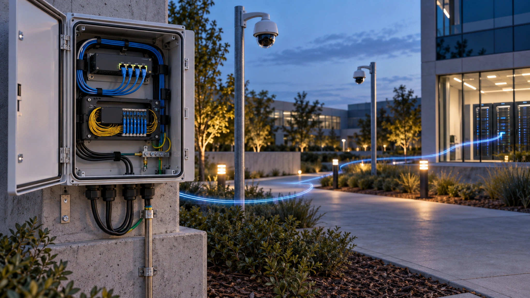
This guide uses the Altronix NETWAYSP41WPX outdoor PoE switch as a catalog-grounded example. Ztronyx lists it as in stock with four ports, two SFP interfaces, outdoor/NEMA4 construction, and fiber connectivity. Altronix's data sheet describes four 30 W PoE+ ports, two 1 Gb SFP ports, and a 120 W aggregate budget. Those are verified capabilities, not permission to skip a site power study.
Reference architecture
Use this traffic path:
camera drops -> outdoor PoE switch -> matched fiber link -> indoor managed switch -> surveillance firewall/VLAN -> NVR or VMS
Separate the design into four boundaries:
- Edge power: the outdoor switch powers only assigned cameras or approved devices.
- Electrical: fiber spans the remote structure-to-building distance.
- Security: a VLAN and routed policy constrain camera communications.
- Operations: monitoring detects loss of power, link, camera, time, or recording.
Fiber is valuable between buildings and detached poles because the optical strand is nonconductive. The remote enclosure still has local AC power and copper camera drops. A qualified designer must address bonding, listed surge protection, branch-circuit protection, lightning exposure, and local codes.
Separate facts, recommendations, and requirements
| Type | Example |
|---|---|
| Verified fact | NETWAYSP41WPX has four PoE+ ports, two SFP ports, and a 120 W total budget |
| Engineering recommendation | Hold normal worst-case PoE demand to 80% of documented capacity |
| Site requirement | Enclosure elevation, grounding, UPS runtime, firewall flows, or flood exposure |
Do not claim that an enclosure rating makes an installation suitable for every coastal, washdown, hazardous, flood-prone, or corrosive location. Verify ratings, mounting hardware, glands, temperature, ventilation, and material compatibility for the actual site.
Prerequisites and survey data
Collect the camera model, firmware, maximum documented power, powered accessories, cable distances, branch circuit, UPS source, runtime requirement, fiber type, strand count, connectors, loss budget, spare strands, environmental conditions, indoor switching, VLANs, routing, monitoring, VMS addresses, required protocols, NTP, DNS, certificate services, logging, and firmware process.
Also identify grounding, bonding, separation, firestopping, and penetration requirements. The standard 100 m Ethernet channel limit applies to ordinary copper camera links unless every component documents another design. Measure the permanent link rather than estimating from a map.
Step 1: Build camera and traffic schedules
Create one row per camera. Record resolution, frame rate, codec, expected average bitrate, configured maximum, stream destinations, analytics, audio, and multicast use. Rain, foliage, traffic, low-light noise, and moving PTZ views can create more traffic than a quiet daytime test.
The uplink calculation includes simultaneous streams, management traffic, protocol overhead, and growth. A 1 Gb SFP is not automatically a 1 Gb recording design; downstream switching, firewall throughput, recorder ingest, and storage write performance are separate constraints.
Prefer unicast unless a tested multicast requirement exists. For multicast, document querier placement, IGMP snooping, receiver count, and failure behavior. Uncontrolled multicast can flood every edge port. Measure traffic while the video wall, mobile clients, analytics, and recorder are simultaneously active.
Step 2: Calculate PoE from worst-case demand
Both aggregate and per-port limits must pass:
design watts = maximum endpoint watts + powered accessory watts
aggregate utilization = total design watts / switch budget
Consider four endpoints with documented or measured worst-case demands of 21 W, 23 W, 24 W, and 18 W. Total demand is 86 W. On a verified 120 W budget, utilization is 71.7%, leaving 34 W of margin. Each endpoint also stays below 30 W.
Four endpoints requiring 30 W consume the entire budget. The arithmetic fits, but there is no reserve. Do not solve this by disabling heaters, infrared, or analytics unless the surveillance requirement still passes. Select more capacity, reduce endpoint count, or use an approved separate power design.
After installation, force or wait for the highest-power state. Daytime wattage is not acceptance evidence for cameras with nighttime IR, heating, wipers, or auxiliary illuminators. Record per-port values and switch temperature as commissioning baselines.
Step 3: Specify a complete fiber channel
Match fiber type, duplex versus single-strand operation, transmit and receive wavelengths, connector, supported distance, optical loss budget, opposite-end optic, switch compatibility, and operating temperature.
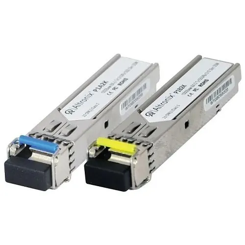
The Altronix P1B2K single-mode SFP shows why pairing matters. Ztronyx lists it as a 1 Gb single-mode transceiver that works with P1A2K. Altronix describes P1A2K/P1B2K as a complementary bidirectional single-strand pair for distances up to 2 km. Two P1B2K units are not a documented pair.
Calculate channel loss from fiber attenuation, connectors, splices, patch panels, and engineering margin. Test installed fiber with suitable optical-loss equipment and retain results. A link LED proves synchronization, not adequate margin. Clean and inspect connectors using the site's approved fiber-safety procedure; never look into a fiber or optic.
Provide spare capacity where the route is expensive to reopen. Spare strands, labeled slack, and documented patch-panel positions are usually cheaper than emergency civil work. Protect fiber bend radius and pulling tension throughout installation.
Step 4: Build the outdoor edge correctly
Mount where technicians can work safely and water cannot pool around entries. Use listed fittings, preserve bend radius, add drip loops, cap unused openings, segregate power as required, and label both ends of each cable. Route data and power so a routine switch replacement does not disturb unrelated terminations.
Outdoor and direct-burial cables address different conditions; a raceway does not automatically make indoor cable suitable outdoors. At building entries, follow transition, grounding, and firestopping rules. The Ztronyx plenum and riser cable guide covers interior spaces, while the authority having jurisdiction decides project requirements.
Use surge protectors and bonding methods selected for the actual exposure. Keep grounding conductors routed according to manufacturer instructions. Fiber isolates the backhaul, not the local camera copper or AC feed. Verify available fault current, disconnecting means, and branch protection with qualified electrical personnel.
Account for thermal behavior. Solar loading can make an enclosure much hotter than ambient, while cold starts may activate several camera heaters at once. Compare the full equipment temperature range with the survey, include power-supply derating where the manufacturer requires it, and do not improvise vents that defeat the enclosure rating.
Step 5: Segment and filter camera traffic
CISA recommends physical or logical segmentation of critical devices. Use a surveillance VLAN with default-deny routing.
| Source | Destination | Permit |
|---|---|---|
| Cameras | NVR/VMS ingest addresses | Documented video and control ports |
| Jump host | Cameras and edge switch | Authorized encrypted management |
| Devices | Approved NTP and DNS relays | Only required services |
| Devices | Monitoring collector | Documented logging and health protocols |
| Cameras | Internet | Deny by default |
Exact ports depend on vendor, firmware, and VMS. Derive them from current documentation and a test segment. Do not paste a broad rule set from another site. Change default credentials, use unique managed credentials, disable unused services, restrict management, and retain encrypted configuration backups.
If ONVIF is needed, create a least-privileged integration account and enable only required services. The Ztronyx ONVIF guide explains why discovery and streaming do not prove full feature compatibility.
Prevent accidental layer-two bridging into user networks. Disable unused switch ports, document trunks and native VLAN behavior, and use DHCP protections or static addressing according to the owner's architecture. Time synchronization deserves explicit monitoring because a camera that records the correct scene with the wrong timestamp can still fail operational needs.
Step 6: Make failures observable and recoverable
Monitor switch reachability, fiber uplink, per-port link, per-port power, and recorder receipt. Ping can work while recording is stopped. Alert on offline devices, repeated port power cycles, high PoE use, uplink errors, NTP offset, certificate expiry, stream loss, storage errors, enclosure tamper, and upstream power failure where supported.
Define who receives each alarm, during what hours, and what response is expected. Alarm storms without ownership are not monitoring. Test escalation after commissioning and periodically thereafter.
Document replacement steps: optic pair, VLAN, port profile, addresses, configuration backup, firmware baseline, spare locations, and escalation contact. A technician should be able to replace a switch or optic without guessing or temporarily connecting the camera network to an uncontrolled LAN.
Failure modes and troubleshooting
Cameras reboot at night
Review PoE logs and measured draw with IR, heaters, illuminators, and analytics active. Verify aggregate and port limits, cable length, conductor quality, terminations, and temperature. Swapping ports may hide but does not fix an overloaded budget.
Fiber is down or one-way
Confirm complementary wavelengths, fiber type, connector cleanliness, strand assignment, and SFP support at both switches. Measure optical power or channel loss instead of repeatedly reseating optics.
Video freezes while ping works
Review recorder ingest, packet loss, uplink errors, firewall state, multicast controls, and bitrate peaks. Capture traffic at both edge and recorder to locate loss. Confirm the VMS is consuming the intended stream profile.
Equipment fails after storms
Preserve logs and failed parts. Have qualified personnel inspect bonding, protectors, grounding, water intrusion, and AC supply. Do not assume fiber makes the entire site surge-proof.
Link flaps during hot afternoons
Compare enclosure and equipment temperature logs, optical levels, supply voltage, and error counters. Inspect solar exposure, seals, and unauthorized field modifications. Correct the environmental design rather than masking alarms.
Acceptance checklist
- SKUs, firmware, optics, and environmental ratings match the approved submittal.
- Copper and fiber paths have labeled, retained test results.
- Complementary wavelengths and switch compatibility are documented.
- Worst-case PoE calculations pass with reserve.
- Nighttime high-power operation causes no cycling.
- Camera VLAN has no unintended user-network or internet route.
- Required VMS, NTP, DNS, logging, and management flows pass; others fail.
- Credentials, time, certificates, firmware, and backups are verified.
- Loss of uplink, camera, recording, and power generates useful alerts.
- Operators can find and export a test event from every camera.
- Seals, entries, grounding, surge protection, and service access pass inspection.
- As-builts and recovery procedures match the installed system.
Buyer and operator guidance
Buy a tested channel, not compatible-looking parts. For NETWAYSP41WPX, include the correct paired optics, fiber, indoor termination, power source, protectors, enclosure accessories, and monitoring integration in the bill of materials and commissioning script.
Operators need an as-built port map, VLAN schedule, firewall rules, baseline power readings, fiber results, configuration exports, firmware inventory, spares, and recovery runbook. Review the installation after it experiences darkness, heat, cold, and severe weather. Reliability comes from verified margins and observable failure, not from a weatherproof label alone.
Sources
- Altronix NETWAYSP41WPX data sheet
- Altronix P1AB2K complementary BiDi kit
- CISA: Layering Network Security Through Segmentation
- NIST CSWP 28: Security Segmentation
- IEEE 802.3 Ethernet Working Group
Frequently Asked Questions
Use fiber between buildings, poles, gates, and other electrically separate locations when practical. Fiber does not conduct surge current and can span longer distances than standard copper Ethernet. Copper remains appropriate for final camera drops within documented limits and with properly designed PoE and surge protection.
A practical target is to keep normal worst-case camera load at or below about 80 percent of the documented PoE budget. Confirm the load with infrared, heaters, wipers, and accessories active. This reserve is an engineering recommendation, not a manufacturer requirement.
No. Altronix identifies P1B2K as one side of a complementary single-strand bidirectional pair and states that it works with P1A2K. Verify wavelength, connector, fiber type, distance, and the opposite-end transceiver before ordering.
Normally no. Place cameras in a restricted surveillance segment and permit only documented flows to the recorder, management services, approved DNS and NTP relays, and explicitly required vendor services.
Test links and PoE under nighttime or forced high-power conditions, verify firewall policy, exercise claimed redundancy, review logs, confirm time synchronization, inspect grounding and seals, and export an incident clip from every camera.
Related Products
Related Articles
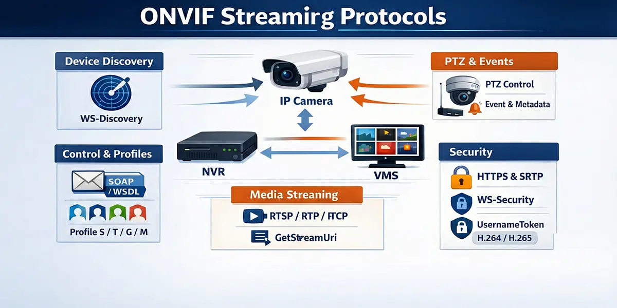
ONVIF Streaming Standard | Architecture, Discovery, RTSP & Security
ONVIF powers cross-vendor interoperability for IP cameras by standardizing discovery, configuration, and streaming setup. This guide breaks down the SOAP/WSDL control plane, WS-Discovery device detection, Media profiles and GetStreamUri, and the RTSP/RTP/RTCP media stack—plus PTZ, events/metadata, and security (WS-Security, HTTPS/SRTP) with a look toward WebRTC.
Read Article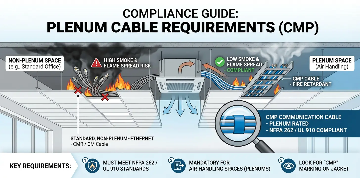
Plenum Cable Requirements (CMP) — Where It’s Required (and Why)
Covers CMP plenum cable requirements for low-voltage work: where it’s required in air-handling spaces, how CMP differs from CMR/general-purpose ratings, and how to verify markings and listings. Highlights common inspection issues and best practices for selecting compliant materials.
Read Article