ONVIF Streaming Standard | Architecture, Discovery, RTSP & Security
Technical Architecture and Protocol Specifications of the ONVIF Streaming Standard
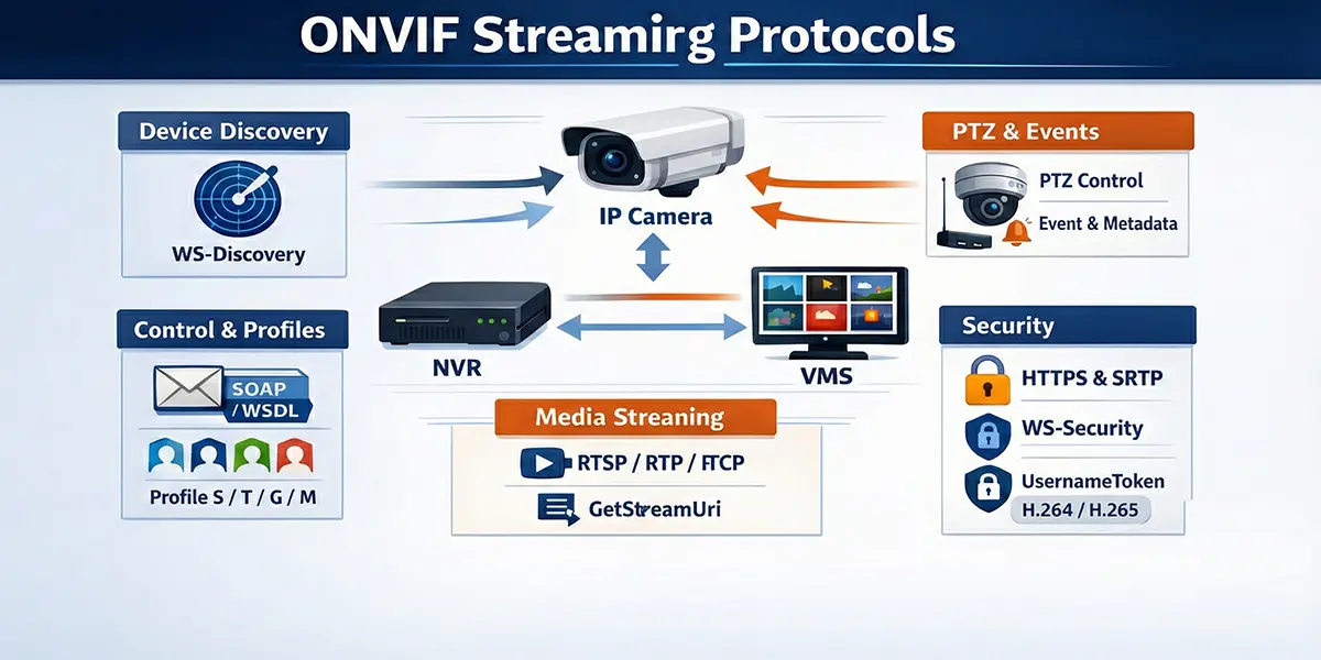
The transition from localized analog surveillance to globally distributed Internet Protocol (IP) based security networks necessitated a fundamental shift in the interoperability paradigm. Proprietary vendor-locked protocols characterized the early digital video market, creating significant hurdles for system integrators and end-users. In 2008, the establishment of the Open Network Video Interface Forum (ONVIF) by Axis Communications, Bosch Security Systems, and Sony Corporation provided the industry with a standardized framework for the interface of physical security products.1 This standard utilizes an extensive Web Services framework to abstract hardware complexities, enabling disparate devices—including IP cameras, video encoders, and network video recorders (NVRs)—to communicate seamlessly with Video Management Software (VMS).3 The core of the ONVIF streaming standard resides in its ability to define standardized interfaces for device discovery, configuration, and real-time media transport through a strictly typed, contract-based architecture.5
Theoretical Foundation and Web Services Framework
The ONVIF specification is built upon an established hierarchy of Web Services standards, primarily utilizing XML 1.0 for data description, SOAP 1.2 for message exchange, and WSDL 1.1 for service definitions.3 This architecture ensures that the standard remains transport-neutral and highly extensible. By employing a service-oriented architecture (SOA), ONVIF separates the management of the device from the transmission of the media, allowing for a robust control plane that can operate over standard network infrastructures, including those protected by firewalls and proxies.8
SOAP 1.2 and XML Serialization
The utilization of Simple Object Access Protocol (SOAP) 1.2 is central to the ONVIF communication layer. SOAP provides a structured envelope for requests and responses, allowing for complex data types and comprehensive error handling.3 Unlike previous versions of SOAP, version 1.2 offers improved binding to HTTP and more flexible processing of XML namespaces.3 The serialization of data into Extensible Markup Language (XML) ensures that the message format is human-readable and platform-independent, which is critical for an industry standard intended for use across diverse embedded operating systems.4
The communication process is initiated by a client sending a SOAP request to a specific service endpoint on the device. For management tasks, this endpoint is typically the Device Service, often located at a standardized URI such as http://<device_ip>/onvif/device_service.9 The device, acting as the server, parses the XML payload, executes the requested operation, and returns a SOAP response containing the result or a structured fault message if the operation fails.11
WSDL and Contract-Based Interface Definition
The Web Services Description Language (WSDL) is used to define the interface of each ONVIF service.3 A WSDL file acts as a technical contract, specifying the available operations, the structure of the input and output messages, and the network endpoints.3 For developers, these WSDL files are the primary source of truth for implementing ONVIF functionality. Toolkits such as gSOAP are frequently employed to consume these WSDL files and automatically generate C/C++ source code that handles the underlying XML serialization and SOAP message exchange.3
The generation process involves tools like wsdl2h, which converts WSDL and XSD (XML Schema Definition) files into a C/C++ header file that defines native structures and function signatures.3 This abstraction allows developers to focus on high-level application logic—such as initiating a PTZ move or requesting a stream URI—rather than the low-level mechanics of constructing XML envelopes and managing HTTP headers.3
| Namespace Prefix | URI Reference | Functional Area |
|---|---|---|
| tds | http://www.onvif.org/ver10/device/wsdl | Device Management Service |
| trt | http://www.onvif.org/ver10/media/wsdl | Media Service (Legacy/Media1) |
| tr2 | http://www.onvif.org/ver20/media/wsdl | Media2 Service (Advanced) |
| tt | http://www.onvif.org/ver10/schema | Common Data Types and Schemas |
| tptz | http://www.onvif.org/ver20/ptz/wsdl | Pan-Tilt-Zoom Control |
| tev | http://www.onvif.org/ver10/events/wsdl | Event Handling and Notifications |
| timg | http://www.onvif.org/ver20/imaging/wsdl | Imaging and Exposure Control |
| wsnt | http://docs.oasis-open.org/wsn/b-2 | WS-BaseNotification |
| wsse | http://docs.oasis-open.org/wss/2004/01/oasis-200401-wss-wssecurity-secext-1.0.xsd | Web Services Security |
The use of these namespaces ensures that different ONVIF services can coexist within the same XML document without name collisions, which is essential for complex operations like media profile configuration.3
Technical Mechanics of Device Discovery
The discovery phase is the initial and arguably most critical step in establishing an ONVIF connection. To achieve true "plug-and-play" capability within a local area network, ONVIF mandates the use of the WS-Discovery protocol.4 This protocol allows clients to find devices without prior knowledge of their IP addresses, which is vital for dynamic environments where devices may receive addresses via DHCP.4
WS-Discovery Protocol and Multicast Operations
WS-Discovery operates primarily over UDP port 3702 using a standardized multicast address: 239.255.255.250 for IPv4 and FF02::C for IPv6.1 The discovery process involves several specific message types designed to minimize network load while ensuring reliable detection.14
In the Ad-Hoc mode, which is the standard implementation for local security subnets, the discovery process follows a specific handshake 14:
- Probe: The client broadcasts a multicast Probe message. This message typically includes filters based on Types (e.g., dn:NetworkVideoTransmitter) and Scopes (e.g., location, hardware model, or name) to narrow down the search.1
- ProbeMatch: Any device on the network that matches the criteria specified in the Probe responds with a unicast ProbeMatch message.14 This response is critical as it contains the XAddrs—a list of URLs for the device's management service—and the MetadataVersion.1
- Hello: When a device first connects to the network or powers up, it proactively sends a multicast Hello message to announce its availability.14 This allows clients to detect new devices without constant polling.
- Bye: When a device is gracefully shut down, it should send a multicast Bye message to inform clients that it is no longer reachable, reducing the likelihood of stale entries in the client’s device registry.14
Managed Discovery and Discovery Proxies
In large-scale enterprise environments where network segmentation is common, multicast traffic is typically blocked by routers. To overcome this, WS-Discovery supports a Managed mode.14 A Discovery Proxy (DP) is deployed as a central registry that bridges multiple subnets. Devices send unicast Hello/Bye messages to the DP, and clients send unicast Probes directly to the DP.14 If a DP is present on a network, it will respond to multicast probes with an announcement for itself, signaling clients to switch to managed (unicast) operation to reduce multicast overhead.14
The implication for system integrators is that in small installations, discovery is automatic and seamless, whereas in large-scale multi-vlan environments, a discovery proxy or manual IP configuration is required to ensure connectivity between the VMS and the edge devices.15
The ONVIF Profile Architecture
To simplify the vast array of possible features and ensure compatibility across manufacturers, ONVIF organizes its specifications into "Profiles".5 A profile represents a specific set of functional requirements that both a device (the producer) and a client (the consumer) must support to be considered conformant.5
Profile S: Core Streaming Foundation
Profile S is the most ubiquitous profile, designed for basic IP-based video systems.5 It focuses on the fundamental requirements for live video streaming, including H.264 compression, PTZ control, and audio input.5 For a device to be Profile S conformant, it must be able to send video data over an IP network to a client, while a Profile S client must be able to configure and request that stream.5
| Feature | Requirement (Device) | Requirement (Client) |
|---|---|---|
| Video Streaming (H.264) | Mandatory | Mandatory |
| Video Streaming (MJPEG) | Mandatory | Mandatory |
| Audio Streaming (G.711) | Conditional | Conditional |
| PTZ Configuration | Conditional | Conditional |
| Multicasting | Conditional | Conditional |
| Relay Outputs | Conditional | Conditional |
| Device Discovery | Mandatory | Conditional |
The "Conditional" designation indicates that the feature is mandatory only if the physical device possesses that capability (e.g., a fixed camera does not need to support PTZ operations to be Profile S conformant).5
Profile T: Advanced Video and Metadata
Profile T, released in 2018, significantly advances the streaming capabilities by introducing mandatory support for H.265 compression and metadata streaming.19 Unlike Profile S, which focused primarily on the transport of pixels, Profile T recognizes the increasing importance of analytics and security in modern surveillance.19
Significant improvements in Profile T include 21:
- Compression: Mandatory support for H.264 and H.265, enabling higher resolutions and lower bandwidth consumption.
- HTTPS Streaming: Enhanced security through mandatory support for streaming over encrypted connections.
- Bi-directional Audio: Supports both audio in (from camera) and audio out (to camera backchannel).
- Metadata Configuration: Provides standardized ways to configure and stream analytics results, such as motion regions and tampering events.
- On-Screen Display (OSD): Mandatory OSD configuration support for devices.
Profile G and M: Storage and Intelligence
Profile G addresses the needs of edge storage, defining how a client should configure, search, and retrieve recorded video from a device's internal storage (e.g., an SD card).6 This is vital for "decentralized" surveillance systems where the NVR may only pull video during playback or after a network failure.
Profile M is the latest major addition, focusing on the standardization of analytics metadata.6 It provides a framework for communicating smart features such as object classification (human, vehicle), license plate recognition (LPR), and facial recognition.23 Profile M also introduces support for MQTT, allowing security cameras to act as IoT sensors that can trigger actions in smart building systems via an IoT platform.6
Media Service and Stream Negotiation
The transition from device management to active streaming is facilitated by the Media Service.4 This service handles the negotiation of stream parameters and the generation of the URI used by the RTSP client.24
Media1 vs. Media2 Services
ONVIF defines two versions of the media service: the legacy Media1 (trt) and the modern Media2 (tr2).4 Media2 provides a more modular architecture, separating the stream configuration from the source configuration more cleanly, which allows for greater flexibility in multi-streaming scenarios common in high-end 4K cameras.4
In Media2, a Media Profile serves as the central container for all stream settings, including 4:
- Video Source Configuration: Defines the sensor input (resolution, framerate).
- Video Encoder Configuration: Defines the compression (codec, bitrate, GOP size).
- Audio Source and Encoder Configurations.
- Metadata Configurations: Defines which analytics data is included in the stream.
- PTZ Configurations: Associates a PTZ node with the profile.
The GetStreamUri Operation
To initiate a stream, the client performs a GetStreamUri call.4 The request must include a ProfileToken and a StreamSetup object.24 The StreamSetup defines the desired transport chain, such as RTP-Unicast or RTP-Multicast, and the underlying network protocol, such as UDP, TCP, or HTTP.25
The device responds with a URI that typically points to the RTSP service on the device.24 For example: rtsp://192.168.1.10:554/onvif/profile1
It is important to note that the port returned in the URI may vary. While 554 is the standard RTSP port, many devices use non-standard ports or multiplex the RTSP service over the same port as the web service when tunneling is requested.7
Mechanics of Real-Time Transport: RTSP, RTP, and RTCP
While ONVIF uses SOAP for the control plane, the high-bandwidth media transmission is delegated to a dedicated real-time protocol stack: RTSP, RTP, and RTCP.2 This separation is crucial for performance; SOAP is far too verbose and computationally intensive for the delivery of 30 frames-per-second video.2
RTSP as the Session Controller
The Real-Time Streaming Protocol (RTSP) functions as a "network remote control" for the media server.31 It is an application-level protocol designed to establish and control media sessions.31 RTSP is stateful, meaning the server maintains the context of the session (e.g., current playback position, transport parameters) through a Session ID.19
The standard RTSP handshake in an ONVIF context involves the following methods 7:
- OPTIONS: The client queries the server to determine which RTSP methods are supported.7
- DESCRIBE: The client requests a description of the media. The server responds with a Session Description Protocol (SDP) file.19
- SETUP: The client specifies the transport mechanism for each media track (e.g., "send the video track via RTP over UDP to my port 5000").7
- PLAY: The client instructs the server to begin the transmission of RTP packets.7
- PAUSE: Temporarily halts the stream without ending the session.7
- TEARDOWN: Terminates the session and releases the associated network resources.7
RTP and RTCP: The Data and Feedback Channels
The Real-time Transport Protocol (RTP) handles the actual packetization and delivery of the multimedia data.7 RTP packets include a timestamp and a sequence number, which are essential for the client to reorder packets that arrive out of sequence and to synchronize audio and video tracks.19
Complementing RTP is the Real-time Control Protocol (RTCP).7 RTCP provides out-of-band statistics and control information for the RTP session.19 It provides feedback on the quality of service (QoS), including metrics such as packet loss, jitter, and round-trip delay.19 In ONVIF, RTCP is also used to transmit sender reports that map the RTP timestamp to a wall-clock UTC time, ensuring that forensic timestamps in the VMS are accurate.19
Session Description Protocol (SDP) Integration
The SDP file returned during the DESCRIBE phase is a critical bridge between the ONVIF management layer and the RTSP transport layer.19 It contains metadata about the stream that is not always present in the ONVIF Media Profile, such as 19:
- The number of available tracks (video, audio, metadata).
- The codec-specific parameters (e.g., H.264 profile and level, sprop-parameter-sets).
- The payload type numbers used in the RTP headers.
- The control URIs for each individual track required for the SETUP command.
Network Traversal: Tunneling and Interleaving
One of the significant challenges in real-world IP surveillance is traversing complex network topologies, including firewalls, NAT routers, and proxies.18 Standard RTSP/RTP often fails in these environments because it typically requires the server to open new UDP connections back to the client, which are blocked by most default firewall configurations.18
RTSP over HTTP/HTTPS Tunneling
To bypass these restrictions, ONVIF supports RTSP over HTTP/HTTPS tunneling.18 This technique encapsulates the entire RTSP session within standard web traffic, usually on port 80 or 443.18 The implementation follows a dual-socket mechanism 18:
- GET Session (The Data Pipe): The client establishes an HTTP GET connection to the device. The device responds with a 200 OK but does not close the connection.18 This socket is used by the device to send RTSP responses and the actual media data (RTP packets) back to the client.18
- POST Session (The Command Pipe): The client establishes a second HTTP POST connection. This socket is used exclusively by the client to send RTSP commands (SETUP, PLAY, etc.) to the device.18
Both connections are linked using an x-sessioncookie header.35 This approach is robust because it appears to the network as standard web browsing traffic, but it introduces a small amount of overhead compared to raw UDP.7
Interleaved RTP over TCP
An alternative to HTTP tunneling is the interleaving of RTP data directly into the RTSP TCP connection.31 In this mode, instead of using separate ports for media, the RTP packets are multiplexed onto the same socket used for RTSP commands.31
The packet structure for interleaved data uses a 4-byte prefix 31:
- Dollar Sign ($): A constant 1-byte value (0x24) used as a magic number.
- Channel Identifier: A 1-byte value indicating whether the packet is RTP or RTCP and which track it belongs to.
- Length: A 2-byte value specifying the size of the following RTP/RTCP packet.
This method is highly efficient for traversing NATs because it only requires a single outbound TCP connection on port 554 [34].
PTZ (Pan-Tilt-Zoom) Control Architecture
ONVIF provides a standardized interface for controlling the movement and optics of cameras through the PTZ Service.4 The PTZ model is sophisticated, accommodating everything from mechanical high-speed domes to digital PTZ in panoramic cameras.37
Motion Control Models
The PTZ service distinguishes between three primary types of motion control, each requiring different mathematical and logical handling 36:
- Continuous Move: This is a velocity-based control.29 The client sends a velocity vector for Pan/Tilt (pan/tilt vector) and Zoom (zoom factor). The camera begins moving at that speed and continues until the client sends a Stop command or a pre-defined timeout is reached.29 Velocity is typically expressed as a normalized value between -1.0 (max speed left/down/out) and 1.0 (max speed right/up/in).29
- Absolute Move: This is a position-based control.36 The client specifies a target coordinate within a defined coordinate space.36 This is used for "Click-to-Center" features or for automated guard tours where the camera must move to a specific known orientation.38
- Relative Move: The client specifies a translation relative to the current position.36 For example, "tilt up by 0.1 units".29
Coordinate Systems and Normalization
A fundamental strength of the ONVIF PTZ service is the use of normalized coordinate spaces.36 Because every camera has different mechanical limits and resolutions (e.g., one camera might have 10,000 steps for a full rotation, while another has 3,600), ONVIF abstracts this into a range of -1.0 to 1.0 for the pan and tilt axes.36 This allows a VMS to implement a single joystick interface that works across all vendors.37
Advanced cameras may also support Spherical Coordinates (degrees) or FOV (Field of View) Coordinates, which are useful for integrating with Geographic Information Systems (GIS) to point a camera at a specific latitude and longitude.37
Analytics, Events, and Metadata Streaming
Modern IP surveillance has evolved from passive recording to proactive intelligence. Profiles T and M provide the standardized framework for delivering this intelligence through event notifications and metadata streams.6
The ONVIF Eventing Framework
ONVIF utilizes the WS-BaseNotification standard for its eventing model.43 Events are categorized using a hierarchical topic tree (e.g., tns1:VideoSource/MotionAlarm).44 There are two primary delivery mechanisms 43:
- Base-Notification (Push): The client (subscriber) provides a URL to the device (publisher). When an event occurs, the device initiates an outbound SOAP Notify request to the client.4 This is low-latency but requires the client to have a static, reachable IP address and open firewall ports.
- Pull-Point (Pull): The client creates a subscription and is given a unique SubscriptionId.12 The client then periodically calls the PullMessages operation to "pull" any events that have occurred since the last request.12 This is the most common implementation in the industry because it works behind NATs and firewalls without special configuration.43
Metadata Stream Integration
While events are discrete occurrences, metadata is a continuous stream of information synchronized with the video.4 In a Profile T or M device, metadata is delivered as a separate RTP track interleaved with the video and audio.23
The metadata payload is an XML document with a root node of tt:MetaDataStream.42 To manage the bandwidth of verbose XML, ONVIF supports GZIP compression for the metadata track.42 The stream can contain 23:
- Analytics Data: Bounding boxes for detected objects, object types (human, car), and confidence scores.
- PTZ Status: The current position of the camera motors.
- Dynamic OSD: Information to be overlaid on the video by the client.
Security Architecture and Cryptography
Security in ONVIF is multi-layered, protecting both the control commands and the media streams.1
WS-Security and UsernameToken Authentication
For SOAP-based management, ONVIF mandates the use of the WS-Security UsernameToken profile.1 This mechanism ensures that credentials are never sent in plain text, even over non-encrypted HTTP connections.1
Each request must include a security header with four components 1:
- Username: The account name.
- Nonce: A random string of bytes generated by the client to prevent replay attacks.1
- Created: A UTC timestamp of the request.1
- PasswordDigest: A SHA-1 hash of the concatenated nonce, timestamp, and password.1
The calculation of the digest is highly sensitive to the format of the input data. Specifically, the nonce must be processed as raw bytes (not its Base64 representation) when hashing.49 If the camera's clock is not synchronized with the client's clock, the Created timestamp will fall outside the camera's validity window, and the request will be rejected.24
Media Stream Security (HTTPS and SRTP)
For the media plane, Profile T introduced mandatory support for RTSP over HTTPS.21 This provides a secure tunnel for the RTSP commands and the interleaved RTP data using TLS.21 In scenarios where UDP transport is required but security is still paramount, the standard supports SRTP (Secure Real-time Transport Protocol), which provides encryption and authentication for the RTP packets themselves.31
Performance Analysis: SOAP vs. Binary Protocols
A frequent point of technical discussion in the ONVIF community is the overhead introduced by the SOAP/XML architecture.32 While XML is excellent for interoperability, it is significantly less efficient than binary protocols used in other domains.32
Benchmarking Payload and Latency
Research into SOAP performance on embedded devices reveals substantial overhead compared to protocols like CORBA, gRPC, or binary-serialized RMI.32
| Metric | SOAP (XML) | REST (JSON) | Binary (CDR/FIX) | gRPC (Protobuf) |
|---|---|---|---|---|
| Payload Size | 100% (Baseline) | 60% - 80% | 20% - 50% | 15% - 30% |
| Encoding Latency | 10x - 20x | 4x - 6x | 1x (Reference) | 1.1x |
| Decoding Latency | 50x - 100x | 5x - 10x | 1x (Reference) | 1.2x |
| Memory Footprint | High | Medium | Low | Low |
The primary sources of SOAP overhead include 32:
- Verbosity: XML tags frequently consume more bytes than the actual data they contain.
- Base64 Encoding: Non-text data (like nonces) must be Base64 encoded, increasing its size by ~33%.
- Parsing Complexity: Building a DOM (Document Object Model) tree for a SOAP response requires significant CPU cycles and memory, which can be a bottleneck on low-power IP cameras.32
Mitigating Overhead in Embedded Systems
To address these concerns, high-performance ONVIF implementations utilize XML Pull Parsers (like the one in gSOAP) that process the XML stream tokens as they arrive, rather than loading the entire message into memory.3 Furthermore, by restricting SOAP to the control plane and using binary RTP for the media plane, ONVIF ensures that the overhead of the standard does not impact the real-time performance of the video stream.2
Implementation Strategy and Development Toolkits
For developers, the complexity of ONVIF makes the choice of toolkit critical. The two most common paths are the C/C++ gSOAP toolkit and the Python Zeep-based clients.3
The gSOAP Workflow
The gSOAP toolkit is the industry standard for embedded ONVIF development.3 It provides a complete compiler suite (wsdl2h and soapcpp2) that automates the generation of SOAP 1.2 proxies and servers.3
The implementation steps for a gSOAP-based ONVIF client are 3:
- Header Generation: Run wsdl2h on the ONVIF WSDL files, using a typemap.dat file to ensure correct namespace mapping.
- Stub Generation: Run soapcpp2 on the generated header to create the C++ classes that handle the XML communication.
- WS-Security Integration: Include the wsseapi.c and smdevp.c plugins to handle the PasswordDigest calculation and header generation.3
- Discovery Integration: Include the wsddapi.c plugin to handle multicast UDP probes and responses.3
Python and High-Level Integration
For VMS developers and researchers, Python provides a more rapid development cycle.41 The python-onvif-zeep library is a popular choice, utilizing the Zeep SOAP client to dynamically parse WSDLs and execute operations.41
A typical Python integration for PTZ control follows this pattern 41:
from onvif import ONVIFCamera
mycam = ONVIFCamera('192.168.1.50', 80, 'admin', 'password')
ptz = mycam.create_ptz_service()
media = mycam.create_media_service()
profile = media.GetProfiles()

# Perform a continuous move
request = ptz.create_type('ContinuousMove')
request.ProfileToken = profile.token
request.Velocity.PanTilt.x = 0.5  # Pan right
ptz.ContinuousMove(request)
This high-level approach abstracts the XML entirely, making it ideal for integration with machine learning frameworks like OpenCV or TensorFlow for intelligent video analytics.20
Systemic Pitfalls and Interoperability Challenges
Despite the rigor of the ONVIF specifications, real-world interoperability is often complicated by vendor-specific interpretations and incomplete implementations.20
Common Compatibility Issues
- Mandatory vs. Optional Features: Many integrators assume a "Profile S camera" will support all Profile S features.20 However, features like Absolute Move or Audio are conditional.20 If a camera lacks the hardware, it will simply return a "Feature Not Implemented" fault, which the VMS must handle gracefully.12
- Namespace Deviations: Some older or budget cameras may use incorrect namespace URIs or fail to include mandatory mustUnderstand attributes in SOAP headers, causing standards-compliant clients to reject the messages.25
- Token Persistence: The ProfileToken and ConfigurationToken values are intended to be persistent, but some devices may change them after a reboot or firmware upgrade, breaking existing VMS configurations.24
- RTSP Port Multiplexing: While the ONVIF GetStreamUri response should provide the correct port, some devices incorrectly return a URI for port 554 while actually requiring port 80 (HTTP tunneling) or a proprietary port.28
Strategies for Robust Integration
To build a robust ONVIF-compatible system, developers should follow a "discovery-first" philosophy:
- Always Query Capabilities: Use GetServices and GetServiceCapabilities to build a dynamic map of what the specific device can actually do.24
- Handle Faults Proportionally: Distinguish between a transient network error and a permanent "Operation Not Supported" fault.1
- Clock Synchronization: Implement a mechanism to periodically sync the system clock with the camera clock to prevent WS-Security authorization failures.24
Future Trajectory: WebRTC and Beyond
The ONVIF standard continues to evolve to meet the needs of the modern web and cloud era. The release of version 24.06 in June 2024 marked a significant milestone with the introduction of the WebRTC specification for peer-to-peer video streaming.19
Transition to Web-Native Protocols
The inclusion of WebRTC addresses a major limitation of RTSP: its inability to stream directly to modern web browsers without heavy plugins or server-side transcoding (like HLS or DASH).33 WebRTC provides 19:
- Low Latency: Sub-second latency optimized for interactive use cases.
- NAT Traversal: Built-in STUN/TURN support for seamless cloud connectivity.
- Browser Compatibility: Native support in Chrome, Firefox, and Safari without additional software.
As the industry moves toward VSaaS (Video Surveillance as a Service), the role of ONVIF will likely shift from managing local connections to providing the standardized signaling required to establish secure, encrypted WebRTC links between edge devices and cloud-based VMS platforms.19
Conclusion
The ONVIF streaming standard represents a monumental achievement in industry cooperation, transforming a fragmented market into an interoperable ecosystem. By grounding its architecture in mature Web Services standards like SOAP and WSDL, while delegating heavy lifting to high-performance transport protocols like RTSP and RTP, ONVIF has successfully balanced the competing needs of management flexibility and streaming performance. While the overhead of XML remains a technical challenge for embedded devices, the continued evolution toward Profiles T and M, and the recent embrace of WebRTC, ensure that ONVIF remains the foundational standard for the next generation of intelligent, cloud-connected security systems. For the professional peer, a deep understanding of these protocol mechanics—from the cryptographic nonce in a security header to the dual-socket mechanism of an HTTP tunnel—is essential for navigating the complexities of modern digital surveillance.
Frequently Asked Questions
No. ONVIF conformance only guarantees interoperability for the features defined within specific ONVIF Profiles (S, T, G, M, etc.). Vendor-specific features like Axis Zipstream, Hanwha WiseStream, proprietary analytics, and edge storage triggers are not part of the ONVIF specification. When connecting via ONVIF, you typically get live video streaming, PTZ control, and basic event handling. For full feature access, use the manufacturer's native driver or plugin within the VMS.
Profile S covers IP-based video streaming and PTZ control—it is the baseline for live viewing. Profile T adds H.265 streaming support, imaging settings (exposure, white balance), and motion region configuration. Profile G standardizes edge storage and recording search, allowing a VMS to retrieve recorded video directly from a camera's SD card. Profile M (newer) adds analytics metadata support for AI/ML event data. Most modern cameras support S and T at minimum; verify G and M support if those features are needed.
Common causes include: (1) the ONVIF user account is not enabled or has a different password than the camera's admin account—many cameras require a separate ONVIF user to be created explicitly; (2) the camera and VMS are on different subnets and WS-Discovery multicast (UDP 3702) is blocked by a router or VLAN boundary; (3) the camera's ONVIF version is too old for the VMS (check for firmware updates); or (4) the camera's date/time is significantly out of sync with the VMS server, causing WS-Security token validation to fail. Sync all devices to the same NTP server.
By default, ONVIF uses HTTP for SOAP control messages and RTP/UDP for media streams—both are unencrypted. ONVIF supports HTTPS for the control plane and SRTP for media encryption, but both camera and VMS must support these extensions and be explicitly configured. In practice, most deployments rely on network-level security (dedicated VLAN, 802.1X port authentication, encrypted VPN tunnels) rather than ONVIF-level encryption. For high-security environments, enable HTTPS on the camera, use SRTP where supported, and isolate the camera VLAN from the corporate network.
ONVIF Profile A and Profile C address access control interoperability, but adoption is limited compared to video Profiles S/T. Profile A covers credential-based access control (granting/revoking access, door monitoring), while Profile C covers basic door state and event integration. In practice, most integrators achieve video-to-access-control linking through VMS-level integrations (Genetec Security Center, Milestone XProtect) rather than relying solely on ONVIF. Check with both the camera and access control panel manufacturers for confirmed ONVIF Profile A/C conformance before designing around it.
Related Products